Weather Station
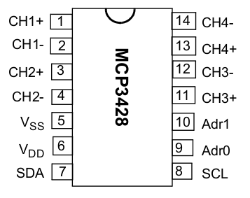
Here is the full Datasheet of the MCP3428 family. The bigest housing SOIC is used.
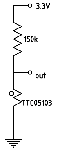
For temperature measurement the NTC thermistor TTC05103 is used. It has a nominal resistance of 10 kΩ at 25℃ and a B constant of 4050 K.
The resistance is calculated with the formula RT=RN*e^(B*(1/T-1/TN). T and TN (the nominal temperature) must be given as absolute temperature in K.
To be able to measure the temperature range from -30℃ to 50℃ a series resistor of 150 kΩ is needed to ensure no higher voltages as 2048 mV
as specified for the inputs of the MCP3428. The following table shows the relation between temperature, resistance of the NTC and the voltage on the
A/D converter, if a 3.3 V source voltage is used.
| Temerature [℃] | -30 | -25 | -20 | -15 | -10 | -5 | 0 | 5 | 10 | 15 | 20 | 25 | 30 | 35 | 40 | 45 | 50 |
|---|---|---|---|---|---|---|---|---|---|---|---|---|---|---|---|---|---|
| Resistance [Ω] | 215984 | 154407 | 111859 | 82054 | 60903 | 45709 | 34669 | 26557 | 20536 | 16023 | 12607 | 10000 | 7993 | 6435 | 5217 | 4257 | 3496 |
| Voltage [V] | 1.947 | 1.674 | 1.410 | 1.167 | 0.953 | 0.771 | 0.620 | 0.496 | 0.397 | 0.318 | 0.256 | 0.206 | 0.167 | 0.136 | 0.111 | 0.091 | 0.075 |
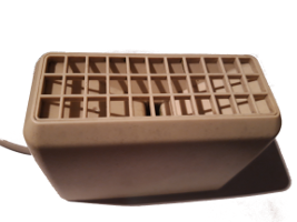
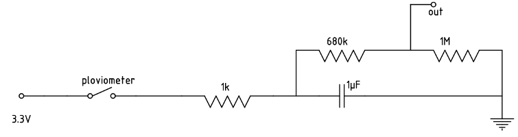
The rain is measured with an old pluviometer as shown in the pictures below. The seesaw changes with every 2 ml of water. The area of the rain collector is about 10 x 3.5 cm². As result 1 impulse means 0.002 l / (0.1 m x 0.035 m) = 0.57 l/m² or 0.57 mm.
 |
 |
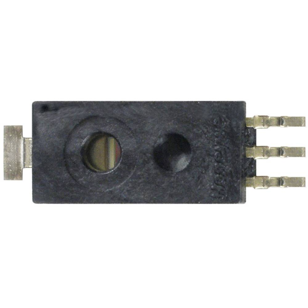
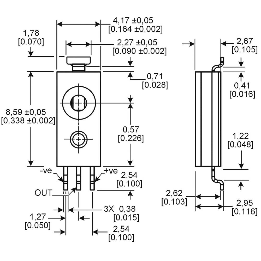
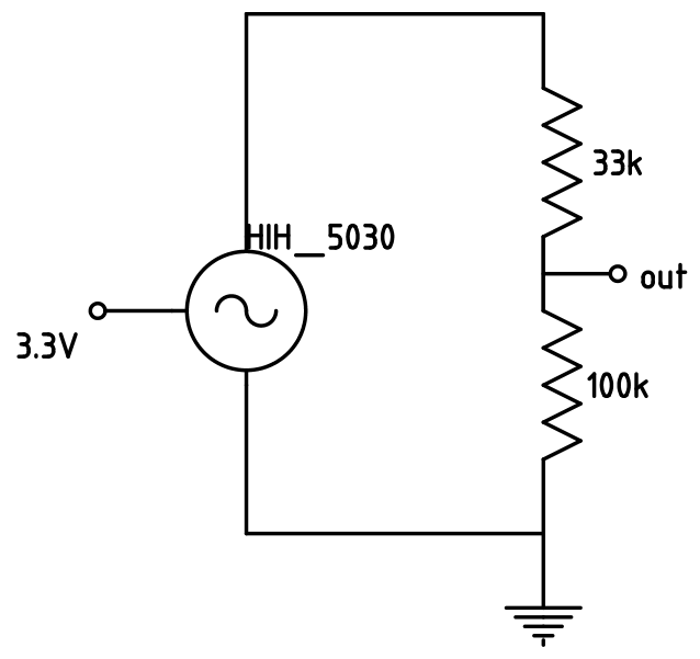
The humidity is measured with a hih-5030-0001 from honeywell Datasheet
It can be used also with 3.3 V and has a voltage output which is highly linear to the humidity. Because the maximum voltage on the output is higher as the 2048 mV, which is defined for the input of the A/D converter, a voltage divider must be used. I used one with 33 kΩ and 100 kΩ.
 |
 |
 |
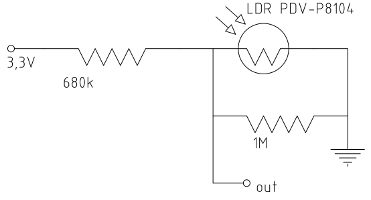
The brightness is measured with the LUNA Optoelectronics PDV-P8104 Fotowiderstand LDR THT. Because a good relation between brightness and resistance
is not given in the datasheet, no conversion table can be made now.
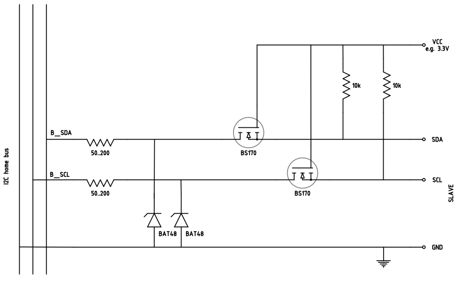
Because the I2C levels of 3.3 V and 5 V don't allow long distances a level shifting to 12 V is done. The following layout shows this shifting circuit and
a protection for voltage pulses higher than 20 V.
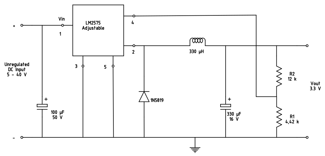
For the voltage supply the LM2575T-ADJ is used. There is also a LM2575 with fixed 3.3 V but I wanted to try the adjustable version to learn for other
projects. The full datasheet is here. The output voltage can be adjusted with R1 and
R2 with the formula Vout = Vref*(1+R2/R1) with Vref = 1.23 V and R1 between 1 kΩ and 5 kΩ. The circuit is designed as shown in the picture:
The SW for reading the values is running in the background program "TS_HomeServer" on my Raspberry Pi 2. This program is running as daemon
and provides a task system with different cycle times and a init part. This daemon is described
here.
All own written SW is stored in the files OwnI2C.cc and OwnI2C.h
and is divided in different classes.
This class summarises all function needed for the I2C communication using the "wiringPI" library.